FireVoxel’s graphical user interface allows user to access
commands and tools. This chapter describes the interface elements and
the main user actions. The appearance and functionality of the interface
can be adjusted using File > User Interface Options.
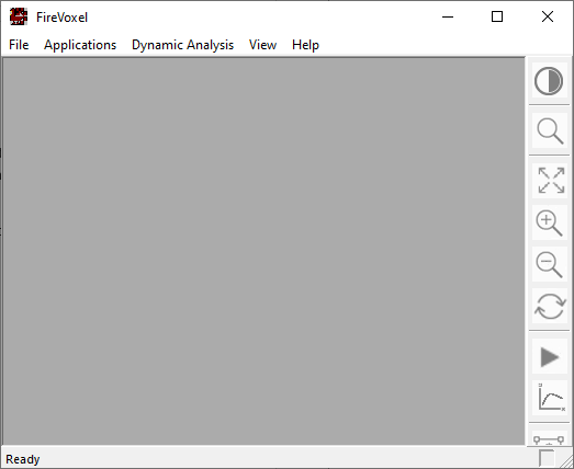
Launching FireVoxel opens the main software window (Fig. 4.1).
It contains the main menu (in the top left corner), status bar (bottom left,
reads Ready in Fig. 4.1), main toolbar
(right, inactive), and minimize/maximize/close buttons (top right).
The main menu contains commands grouped by themes and tasks and
has three levels: tabs, commands, and subcommands.
Commands are activated by clicking the menu tab name, scrolling down
to select the command and clicking it. If commands have subcommands,
these subcommands will be shown as a secondary menu when the command
is clicked. To use a subcommand, select it and click its name.
The main menu tabs and the commands available within these tabs
are different depending on whether any images are open in FireVoxel.
When no images are open in FireVoxel, the main menu contains five tabs:
File, Applications, Dynamic Analysis, View, and Help
(Fig. 4.1). The commands available without
images are used mainly for software testing and batch processing.
The main toolbar, if displayed, is grayed out and
not functional. The visibility of the toolbar is toggled using View >
Show Main Toolbar.
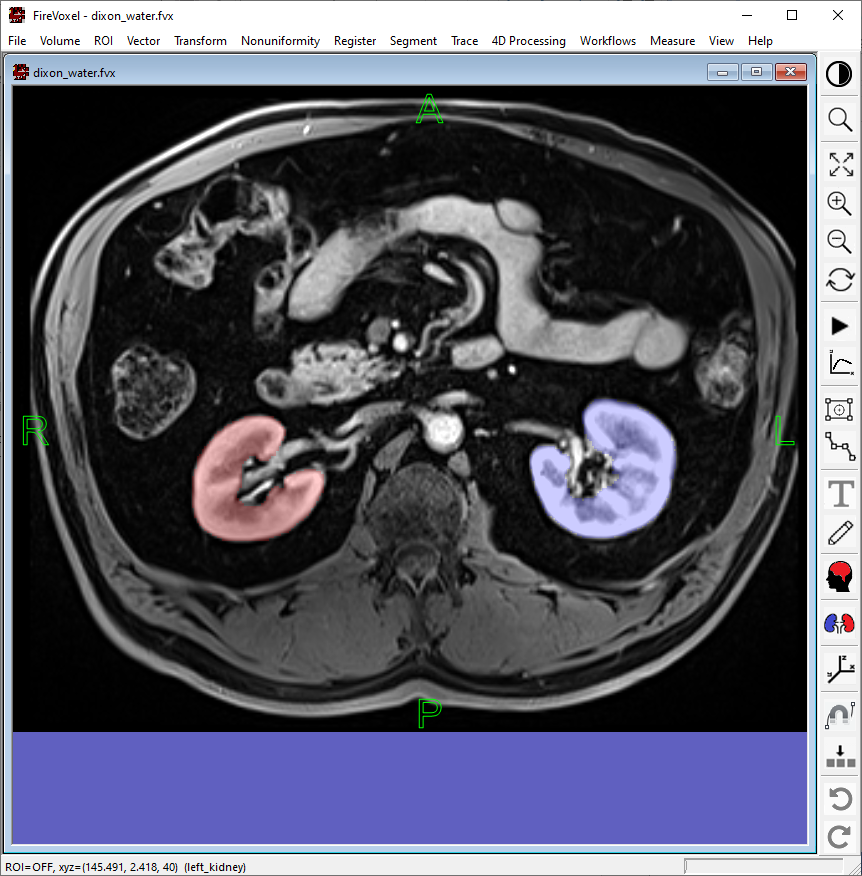
When images are open, the main menu shows the full set of tabs:
File, Volume, ROI, Vector, Transform, Nonuniformity,
Register, Segment, Trace, 4D Processing, Workflows,
Measure, View, and Help (Fig. 4.2).
The document name is shown in the blue title bar.
The main toolbar becomes functional.
The status bar shows the cursor coordinates and other information.
In Fig. 4.2, the status bar reads
ROI=OFF, xyz=[145.491,2.418,40) (left kidney).
Fig. 4.2 FireVoxel’s interface with an image displayed in a document window.
Images are displayed in document windows. Each document window is labeled
with a name in the blue title bar and minimize/maximize/close buttons.
The images are aligned left, and extra space is filled with a solid background
color, which can be customized (see Document background).
Multiple document windows may be opened at once.
Each window must have a unique name. An attempt to open two document windows
with the same names triggers an error message.
To close FireVoxel, select File > Exit.
If any open documents contain unsaved changes, a file-save dialog
will be shown prompting the user to save these documents,
or discard changes, or cancel exiting.
The software can also be closed by clicking the cross in the upper right
corner of the main software window. Again, the user will be prompted
to save or discard any new changes to the currently open documents,
after which the software will be closed.
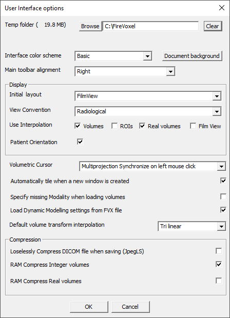
FireVoxel’s user interface can be customized using File >
User Interface Options. This command opens a dialog where the user
can adjust various parameters that control the appearance and functionality
of the interface (Fig. 4.3). The changes of appearance
are applied immediately. The changes of functionality are applied after
the user closes and reopens FireVoxel.
Shows the current location and size of FireVoxel’s Temp folder. The user
can type in a path to a different folder or browse to folder to select
it. Clear button deletes the contents of the Temp folder. The location
of the Temp folder is also shown in Help > Display current UI
configuration.
Offers a dropdown menu with a selection of color schemes: Basic
(default), Aqua, Luna Blue, Obsidian, Silver. The schemes alter the
color of the main software window, main toolbar,
and bottom information bar. Changes are applied immediately.
Opens a color picker for selecting the padding color of the document
windows (the color that fills parts of the window not occupied by the
image). The default color in the basic color scheme is moderate blue HEX
6060c0 (RGB [38, 38, 75], RGB
decimal [96, 96, 192], CMYK [50, 50, 0, 25], Hue/Sat/Lum 160/104/136).
Opens a dropdown menu with a selection of positions where the main
toolbar is docked: Left, Top, Right (default), Bottom.
The change of position is applied immediately. If a toolbar is undocked
and then docked again, it is docked at the position specified by this option.
Opens a dropdown menu with options for the initial layout: FilmView
(default), Single Slice, and Axial, Sagittal, and Coronal projections.
The option is applied upon the next loading of images into FireVoxel.
The option does not affect previously saved FireVoxel documents, which
are opened in the saved view.
Opens a dropdown menu with options for image orientation:
Radiological (axial images are shown with patient’s left side
on the right side of the image); Neurological (left side on the left);
or Original Data (orientation follows the convention of the original data).
Images in NIfTI-1 format with sform and qform entries are displayed
as prescribed by their header entries. Images in NIfTI-2 format are
not compatible with FireVoxel.
Checkboxes for selecting the types of layers and views shown with
interpolation. Options include Volumes (checked by default),
ROIs (unchecked), Real-valued volumes (checked), and Film View (unchecked).
Interpolation makes images appear less grainy.
Checkbox (checked by default) toggling the visibility of green letters
indicating patient orientation: R (right), L (left), A (anterior), P
(posterior), H (head), F (feet).
Opens a dropdown menu with options for the cursor behavior
on orthogonal projection views of the same image
(see Toolbar >
Display orthogonal projections):
Multiprojection Synchronize on left mouse click (default):
Left mouse click on any of the three projections forces the other two views
to display the current cursor position on each of these projections.
The cursor is shown as a cross indicating the intersection of the other
two orthogonal planes.
Regular: Allows the three projections to be displayed
independently, without sensitivity to the mouse clicks or the current
position of the cursor. Each orthogonal projection can be scrolled separately,
without affecting the other two views.
4.4.7. Automatically tile all views when a document is loaded
Checkbox (checked by default) controlling the arrangement of document
windows. When checked, has the effect of View >
Tile after a new document is loaded
(Fig. 9.2).
4.4.8. Specify missing modality when loading volumes
Checkbox (checked by default). ADD DETAILS
4.4.9. Load Dynamic Modelling settings from FVX file
Checkbox (checked by default) to toggle on and off the loading of dynamic modeling
parameters from a FireVoxel document (*.fvx). When the user opens a FireVoxel
document that contains parametric maps generated with Dynamic Analysis models,
the free parameters in the document are compared to the model parameters
in the current configuration of FireVoxel. If these two sets of parameters
do not match, a warning is shown: Loading [*.fvx name] (Model #):Saved number of Free Params differ from current Model.
The document is loaded after the user clicks OK on the warning dialog.
The mismatch may arise, for example, because the dynamic models in FireVoxel
were updated since the maps were generated in the user document.
Opens a dropdown menu with a selection of interpolation methods applied
to the layers and views checked in the Use Interpolation
section. The options include Nearest neighbor, Tri linear (default), Wsinc2,
Wsinc3, and Wsinc4. The interpolation method may be chosen to match
the imaging modality (e.g., Tri linear for CT or Wsinc for MRI).
4.4.11.1. Losslessly Compress DICOM file when saving (JpegLS)
Checkbox (unchecked by default) to toggle on and off the compression
of DICOM files upon saving them in lossless JPEG format (JPEG-LS).
The information on image compression can be found by loading the images
into FireVoxel using File > Open DICOM and examining
the DICOM header entries in lower right part of the
DICOM Tree dialog.
The compression data is recorded in the field (0002,0010) Transfer Syntax UID,
part of the Pixel Data module. See available options in DICOM PS3.18 2022b >
8.7.3 DICOM Media Type Sets.
After the images are loaded into FireVoxel, the Pixel Data module
is removed and Transfer Syntax is no longer displayed as part of the image
information (see Layer Control > Info).
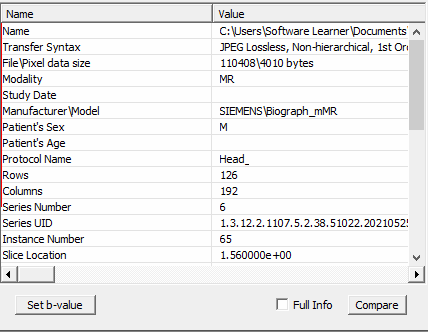
Example (Fig. 4.4): The header of a compressed image shows
Transfer Syntax: JPEG Lossless, Non-hierarchical, 1st Order Prediction.
Fig. 4.4 DICOM Tree header preview for a compressed image: Transfer Syntax
- JPEG Lossless.
For uncompressed images, this field typically reads:
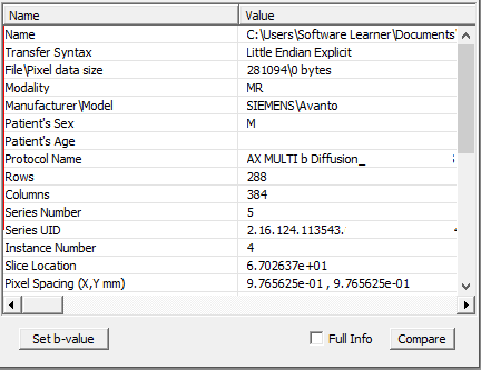
Transfer Syntax: Little Endian Explicit (Fig. 4.5).
Fig. 4.5 DICOM Tree header preview for an uncompressed image: Transfer Syntax
- Little Endian Explicit.
Note:
Compression may interfere with some processing operations.
Compressed images are becoming more common, especially since PACS
increasingly apply compression to exported images by default.
Users are urged to consider whether analyzing compressed images
may affect their processing results.
To convert compressed images into uncompressed images:
Load DICOM images into FireVoxel (see File > Open DICOM).
Verify the compression format during loading (JPEG-LS or similar).
Open File > User Interface Options and make sure that
the Lossless Compression option is unchecked.
Checkbox (checked by default) to toggle on and off the RAM compression
for integer volumes (typically, acquired images, such as MRI, CT, PET, etc.).
By default, images (volumes) are compressed to save RAM. Each slice of the volume
is compressed separately using three-voxel predictive coding combined
with the Huffman entropy encoder. The compressed size of the entire volume
is thus the sum of the sizes of individual slices. See Volume >
Window Center/Width setting >
Timepoint of Maximum Info
for details of the compressed image size in relation to the image information.
To use the uncompressed internal representation, uncheck this box.
In this case, all images will contain the same amount of information.
Checkbox (unchecked by default) to toggle on and off the RAM compression
for real volumes (i.e., usually computed images, such as parametric maps
and results of various analytical operations).
To use the uncompressed internal representation, uncheck this box.
The mouse and keyboard actions described below are employed to interact
with FireVoxel’s user interface. Note that these actions refer
only to a typical two-button mouse (with an optional scroll wheel),
as FireVoxel is a Windows software.
Click – Single left mouse click, unless specified otherwise.
Used to open menus and select commands or launch commands via the main
toolbar icons.
Double-click – Double-left mouse click.
Right-click and double-right click – Right mouse click, single or
double.
Scroll – Turn the mouse up or down. May be used for, e.g., navigating
through the slices of a 3D or 4D image.
Click and drag – Left-click and hold down the left mouse button
and move the mouse. Used, e.g., to draw vector ROIs and move anchor points
on a vector contours.
Right-click and drag – Click and hold down the right mouse button
and move the mouse. Used, e.g., to move a vector contour as a whole.
Hover – Hold the cursor over an object.
Ctrl + left mouse button – Press and hold down the Control key
while pressing the left mouse button and moving the mouse.
Used to draw raster ROIs.
Ctrl + right mouse button – Press and hold down the Control key
while pressing the right mouse button and moving the mouse.
Used to edit raster ROIs.
Up and Down arrow keys – Pressing the Up and Down arrow keys
on the keyboard is used to navigate through slices of a 3D or 4D image
(similar to Scroll).
Right and Left arrow keys – Pressing the Right and Left arrow keys
on the keyboard is used to navigate through the images along the dynamic
dimension of a 4D (dynamic) dataset, such as the different time points
in dynamic contrast-enhanced MRI or CT, or b-values in diffusion-weighted MRI.
Esc – Esc key is used to exit various tools, such as the MagTrace tool
and most of the toolbar tools.
The user interacts with FireVoxel through commands, toolbar
icons, as well as the mouse and keyboard actions. FireVoxel often interacts
with the user through the Image Processing Dialog.
Some FireVoxel commands are executed immediately after being called,
for example, after the user selects a command from the main menu.
Such commands do not require additional input from the user.
Other commands launch standard browse-for-file, browse-for-folder,
or file-save dialogs to select a directory and/or file.
Still other commands open dialog panels that allow the user to configure
the command by selecting its parameters and options.
The dialog panels may range from simple ones with one or few parameters
(for example, Specify Integer) to complex panels with multiple parameters
and options (such as Dynamic Analysis >
Calculate Parametric Map,
or Segment > EdgeWave Basic).
In this case, processing usually starts when the user clicks OK on the dialog.
Some dialog panels combine sections that display interactive information
with sections that enable user actions. An example of such command
is Open DICOM, which opens the
DICOM Tree dialog dialog that contains sections
that display the DICOM structure of a selected directory, DICOM header information,
image preview, and functionality enabling access to various commands.
FireVoxel displays Image Processing Dialog to convey information
in response to some user actions, to send an error message or a warning,
or to display results. Common examples of this dialog include:
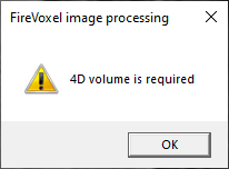
[Image of a certain type] required (Fig. 4.6).
An error message to notify the user that the command was applied
to an image incompatible with this command’s requirements.
For example, if Dynamic Max is applied
to a 3D image, the dialog will notify the user that 4D volume is required.
The user may need to select another layer in the document and consult
this reference for the image type required by the given command.
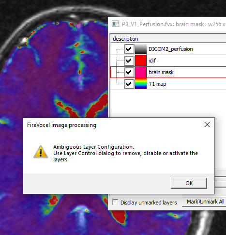
Ambiguous layer configuration (Fig. 4.7).
This message usually appears after a command is called, but it can be
applied to two or more layers in the document.
To resolve the ambiguity, the user needs to examine the layers
in the Layer Control and uncheck
(make invisible) those layers that are not involved in the current operation,
or select an appropriate layer as the active layer.
Example in Fig. 4.7 shows this error when ROI Stats 3D
is called. The ROI layer (brain mask) is the active layer, but there are two
other layers – the image layer (DICOM2_perfusion) and the T1-map – to which
this command may be applied. To avoid this error, the user may uncheck
the visibility of all layers except those to which ROI Stats 3D
should be applied.
Fig. 4.7 Error when a command may be applied to more than one layer.
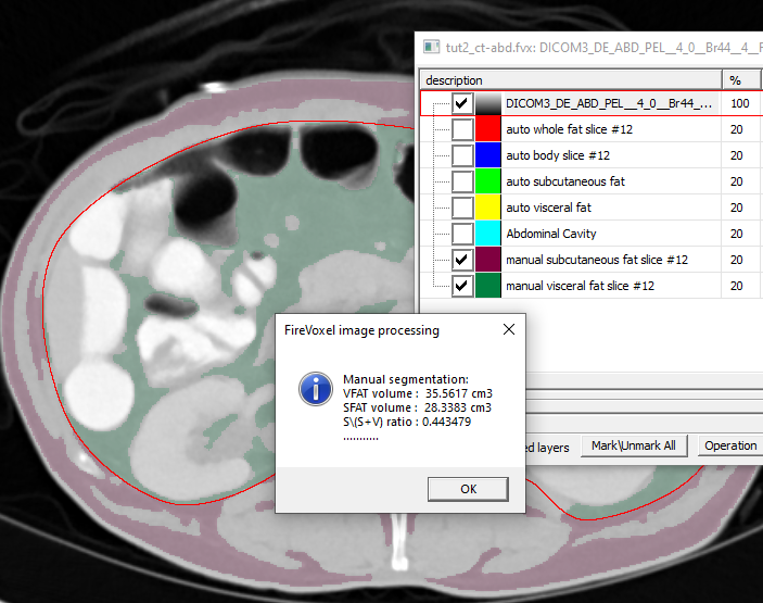
Results (Fig. 4.8).
Some commands return numerical results of measurements or computations
in the form of the Image Processing dialog. These results can be copied
to Clipboard (Ctrl+C) and pasted elsewhere (Ctrl+V).
Example in Fig. 4.8 shows the results of measurements
of subcutaneous and visceral fat segmented on CT.
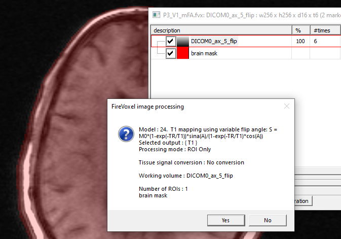
Confirmation dialog (Fig. 4.9).
Many commands under Dynamic Analysis >
Calculate Parametric Map
that perform voxel-by-voxel processing show a confirmation dialog
after the user clicks Process All or Process ROI only.
The confirmation dialog summarizes the operation setup
(including model, outputs, processing mode, critical options, active layer)
and asks the user whether to proceed with the analysis.
This step allows the user to verify whether important and computationally
“costly” processing steps are configured correctly before launching
a potentially time-consuming task.