The Transform tab contains commands that allow users to manipulate the
orientation, position and resolution of the images. The Transform
commands alter the image data and allows the user to save the
transformed images (unlike the View commands that only alter the way the
images are displayed).
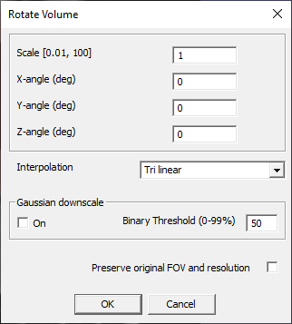
Acts on all layers (image and ROI, visible and invisible). Opens a
dialog (Rotate Volume, Fig. 19.1).
Creates a new document labeled as the original
with _rotated_n suffix (n – integer).
Transforms the source image by applying rotation, scaling, and interpolation.
Rotations are specified by entering angles of rotation, in degrees,
about X, Y, and Z axes into the boxes labeled X-angle (deg), Y-angle
(deg), Z-angle (deg).
Resampling is specified by Scale, a numerical coefficient between 0.01
and 100. The transformed image is resampled to isotropic resolution so
that
.
The Interpolation dropdown menu allows the user to select an interpolation
method. Options include: Nearest neighbor, Tri-linear (default), Wsinc2, Wsinc 3,
and Wsinc 4. The Tri-linear method is preferable for CT and Wsinc methods
are more appropriate for MRI.
If Scale<1 (the image is downscaled), the user may select the downscale
method. Gaussian downscale checkbox selects downsampling by Gaussian
filter (blur) followed by thresholding, with user-specified Binary Threshold
specified in percent (50% by default). As a result, Gaussian downscale may be able
to preserve the image details that would be lost with regular downscale.
If the Gaussian downscale box is unchecked, regular downsampling is used,
and the new voxel values are determined based on a simple average of the original
voxel intensities with filtering at a fixed 50% threshold.
Checking the box Preserve original FOV and resolution suppresses
resampling and retains only rotation. The transformed image will have
the same field of view (FOV) and voxel size as the original, regardless
of Scale.
Acts on all layers. Creates a new document labeled as the original
document with a suffix _RotOrtho_n (n-integer). Opens a dialog panel
(Rotate Volume Orthogonally around Volume Center,
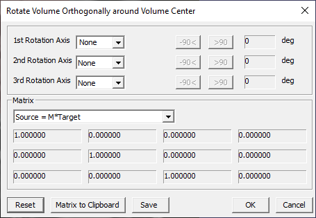
Fig. 19.2). Performs orthogonal rotations around
1st, 2nd, and 3rd rotation axes.
Fig. 19.2 Rotate Volume Orthogonally around Volume Center Panel.
The drop-down menus labeled 1st, 2nd and 3rd
Rotation Axis are used to select X, Y, Z, None axes of rotation.
The buttons labeled -90< deg and >90 deg are used to rotate the volume
in 90-degree increments in counterclockwise or clockwise directions
about a selected axis.
The bottom part of the panel displays the rotation matrix M in one of
the two configurations: 1) Source=M*Target or 2) Target=M*Source.
Reset button clears all entries. Matrix to Clipboard copies the
transformation matrix to clipboard and allows it to be pasted into a
text editor or spreadsheet. Save creates a VTF file (by default in
FireVoxel Temp directory) with information about this transformation.
Requires an image and a set of at least three landmarks
(see Coregister with Landmarks).
If no landmarks are present, shows an error message
(At least 3 points are required in this operation).
If the landmarks are present, shows image processing dialog
with the measurement of the Plane fitting error (mm).
Once the user clicks OK, opens Rotate Volume dialog
(Fig. 19.1) with pre-filled values of
rotations about X, Y, and Z axes. After the user clicks OK,
the command creates a new document window and displays in it
the transformed image. The document is named [original]_Z_[n],
where n is the number of landmarks.
The landmarks are transferred into new document under the same names,
but transformed according to the same rule as the image.
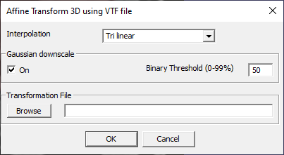
The user can select the Interpolation method (Nearest neighbor, Tri-linear,
Wsinc2, Wsinc 3, Wsinc 4). If the image is downsampled (target
resolution is lower than the original resolution), the user may select
Gaussian downscale and the threshold value (50% by default). The user
must also enter into the Transformation File text box the name of the
previously created .VTF file (or click Browse to open a browse for
file). Pressing OK applies the affine transformation described by the
.VTF file to all visible layers. If the .VTF file does not match the
dimensions of the active layer, FireVoxel shows an error message and the
command is not performed.
Open file save dialog to save the Volume Transform File (with .vtf
extension) with the information about the image transformations. The
file retains the information about a sequence of transformations since
the last document save.
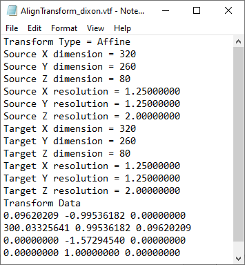
The Volume Transform File (*.vtf) can be opened with a text editor
(Fig. 19.4).
The file contains the transform type (affine), the matrix size and
resolution (voxel size in mm) in X, Y, and Z direction of the source
and target images, and the Transform Data (12 matrix elements of affine
transformation matrix).
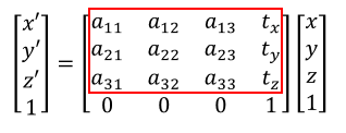
The affine transformations include scaling, rotations, shear, and
translations and can be expressed in matrix form: x’ = A x + t, where x
is the source, x’ is the target, A is the affine transformation matrix
and t is the translation vector. This expression can be rewritten in
terms of matrix elements (Fig. 19.5):
In VTF, the Transform Data are the twelve elements of the affine matrix
(marked with the red box) listed row by row (a11, a12,
a13, tx, a21,…,tz).
Acts on all layers in a document. Opens dialog (Specify Resolution (mm)),
to enter the voxel dimension of the transformed image.
Creates a new document window named after the original window
with an added iso_[number] suffix. The image and the ROI layers,
both visible and invisible, are transformed together and retained
in the transformed image. By default, the resolution is set
to the smallest dimension of the original voxel.
The transformed image has isotropic resolution (cubic voxels).
If the target voxel is larger than the original (i.e., target resolution
is lower than the original), regular downsampling method is used.
To perform Gaussian downsampling (more favorable to small details)
use Rotate and Create new volume.
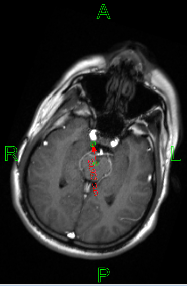
Acts on the active layer and all visible layers. Requires a vector
object (vector – a two-point polyline) (Fig. 19.6).
Shifts (translates) layer(s) by the distance and in the direction specified
by a vector object. Does not create a new document.
Draw a vector (a two-point vector object) using
Insert polyline connecting the origin
and destination of translation. Use View >
Display\Hide curve length
to display the length of the vector, if needed.
Select Vector > Translate using vector command.
The active layer, along with all other visible layers,
is shifted as defined by the vector.
To save the transformation as .VTF file, see
Save Alignment.
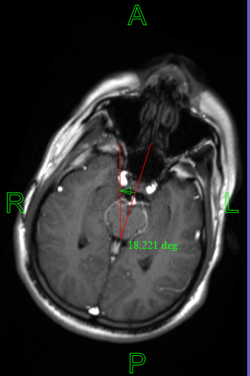
Acts on the active layer and all visible layers. Requires a vector
object, a segment – a 3-point polyline (Fig. 19.7).
Rotates layer(s) by the angle specified by the sector.
Draw a sector – a vector object made of three ordered points (or two
straight segments), using Insert polyline.
The first segment (from the first to the second point)
should be aligned with the original alignment.
The second segment (from the second to third points) should be aligned
with the target direction. The second point is the center of rotation.
Use View > Display\Hide curve length
to display the angle measure of the sector, if needed.
The direction of rotation is indicated by an arrow inside the sector.
Adjust the sector by moving the anchor points after placing them.
Use Vector > Rotate using sector.
The layer(s) are rotated about the center of rotation by the angle indicated
by the sector in the direction from the first segment towards the second segment.
To save the transformation as .VTF file, see
Save Alignment.
Reverses all transformations performed since the last saving of the
document. If several transformations were performed sequentially, all of
them will be undone. The saved .VTF files from these transformations are
not affected.
Requires an image layer. The command extracts the current slice
from the active document, resamples this slice to isotropic resolution
equal to the smallest dimension of the original voxel, and displays
this slice in a new document labeled snapshot.
 .
.