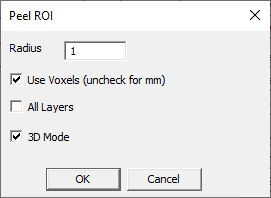
Requires a 3D or 4D ROI. Opens dialog (Peel ROI, Fig. 13.1).
Removes a shell ofspecified width (Radius, by default in voxels,
or in millimeters, byuser choice) from the outer boundary of the active ROI.
Checking All Layers box removes this shell from all ROI layers, visible
and invisible (unchecked by default). Checking 3D Mode results in voxels
removed across slices. This operation writes results to the original
layers and does not create new layers. To retain the original ROI
layers, use Duplicate to create a copy and apply the Peel
command to the copy instead. If the ROI is 4D, the Peel operation is
applied to all dynamic frames.
Requires a 3D or 4D ROI. Opens dialog (Grow ROI). Inverse operation to
Peel operation. Adds a shell of specified width
(Radius, by default in voxels, or in millimeters, by user choice)
from the outer boundary of the active ROI.
Options are the same as for Peel.
Requires a 3D ROI. No parameters. Returns the average depth of the ROI
in millimeters.
13.1.6. Unclump perceived Connected Components to Layers
Requires a 3D ROI. Opens dialog (Specify Peel (mm)). Removes the
original layer and creates one or more ROI layers instead, obtained by
peeling a user-specified width from the ROI boundary.
13.1.7. Unclump perceived Connected Components to Atlas
Requires a 3D ROI. Opens dialog (Specify Peel (mm)). Creates a new,
integer layer, labeled base, with voxel values of 1 inside the ROI
and 0 values outside. The original ROI layer is retained.
Requires a 3D ROI. Opens dialog (Specify PeelGrow). Removes or adds a
shell of user-specified thickness (in millimeters) from the outside
surface of the ROI. Returns the result to the original layer.
Requires a 3D ROI. Opens dialog (Specify Triangle size threshold).
Creates a graph (vector object, made of 3 vertices and connecting
vectors), on the current slice. Triangles of size above user-specified
threshold are marked.
Requires a 3D ROI. Opens dialog with options to specify maximum distance
between ROI edges to be closed and the number of steps. Adds voxels to
ROI edges in a user-specified number and up to maximum distance.
Requires a 3D ROI. Acts on current layer and returns results to the same
layer. Fills 2D contours and extends convex areas across slices. Can be
used to speed up segmentation: contours can be drawn selected slices
(e.g., on every 5th slice) and Fill and Morph command will fill
the contours and extend the ROI to every slice.
Requires an ROI layer. Fills voxels within ROI contours with ROI color.
Contours are filled separately on each slice, but not across slices
(unlike in Morph command).
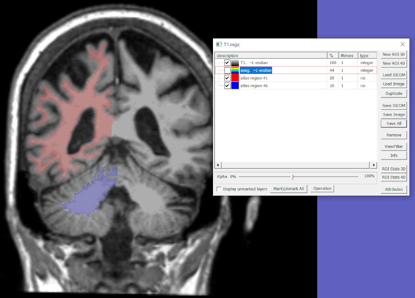
Extracts ROIs with user-selected indices from an atlas segmentation map and
places each ROI in a new, automatically created layer.
Opens dialog to enter a comma-separated list of ROI indices.
Returns ROI layer(s), one per atlas region, each named atlas region [number].
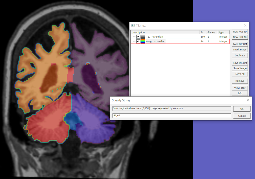
Example: Input data and dialog (Fig. 13.2) and output
(Fig. 13.3) of Extract Atlas ROIs applied to FreeSurfer
atlas segmentation of T1-weighted MPRAGE image of the brain.
Fig. 13.2 Extract Atlas ROI input data (FreeSurfer segmentation of MPRAGE,
T1.mgz (in atlas space), with atlas labels map
aseg.mgz)
and ROI selection dialog to select right cerebral white matter (41)
and right cerebellar white matter (46) regions. Atlas segmentation aseg
is shown in rainbow colormap with [window center, width]=[23.5,47].
Fig. 13.3 Extract Atlas ROI output ROI layers for right cerebral (region 41)
and right cerebellar white matter (region 46).
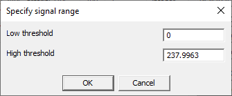
Requires an image layer. Creates a new ROI layer with values of 1 where
image voxels have signal inside the range between the low and high
threshold, which the user can enter in a dialog panel (Specify signal
range, Fig. 13.4).
Voxels outside the range are transparent (VOID). The threshold
values are entered as numerical values into the panel, so the user needs
to determine them beforehand.
Note: This option has been moved here from Volume >
Adaptive Threshold and fully revised.
The function works for integer and real volumes.
Creates a new ROI layer with a binary mask generated by signal thresholding.
For every voxel (x,y,z), the command performs
Otsu thresholding
within the vicinity of a user-specified radius R (in voxels).
The operation creates a mask (ROI) layer and sets the value of the mask
at voxel (x,y,z) to 1 if the signal at this voxel exceeds the threshold
and 0 otherwise.
Note: March 2022 - Currently only a 2D version is available (i.e., only 2D
vicinity is analyzed). The 3D code is working but computationally expensive.
Requires an image layer. Creates two new ROI layers with values based on
the image intensity threshold: ROI A (low portion) with filled voxels where
image intensity is below the threshold value and ROI B (high
portion) with filled voxels where image intensities are above the
threshold value. Opens a dialog panel that allows the user to adjust the
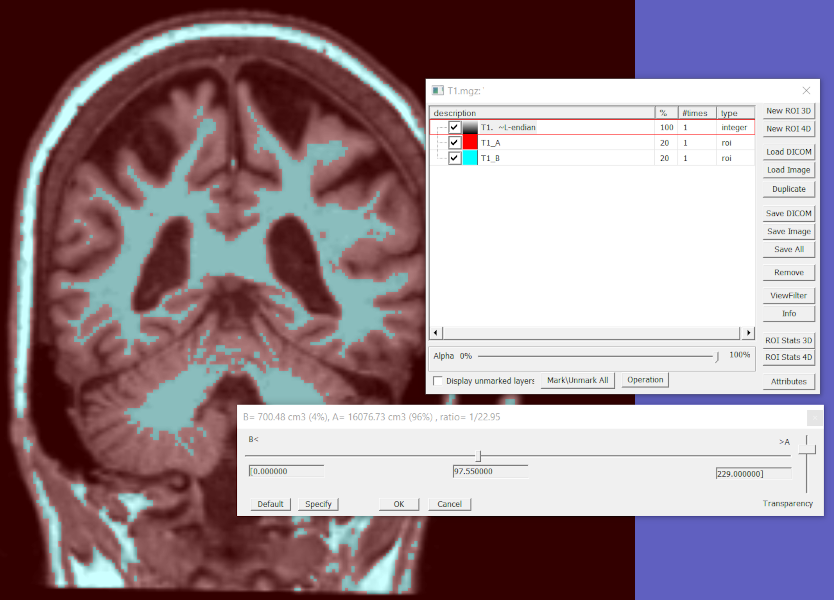
threshold manually based on visual inspection of the ROIs (Fig. 13.5).
Press Cancel or close the panel to cancel and remove the newly created ROI layers.
Fig. 13.5 Split ROI with Threshold dialog with the minimum (0.0) and maximum
(229.0) signal values, and a manually selected threshold (97.55)
splitting the image into ROIs A (low portion, 96%) and B (high portion, 4%).
Dialog Elements:
[Title bar] B=…, A=… – Volumes of ROI A and B (in cm3
and as percent total ROI volume) and the ratio of B/A.
Slider – The horizontal slider can be clicked and dragged right or left
with the mouse to adjust the threshold intensity. Moving the slider to the left
lowers the threshold, decreases ROI A (low portion) and increases ROI B
(high portion). Moving the slider to the right raises the threshold, increases
ROI A and decreases ROI B. The minimum, threshold, and maximum values
are shown below the slider. The resulting ROIs A and B are updated in real time.
The transparency of the ROI layers can be adjusted with the vertical slider
on the right hand side (up – more transparent, down – less transparent).
Specify – Enter a threshold value. The slider is placed at this value.
The command options offer a choice of how the default threshold
is determined:
using initial Threshold – The default threshold is the minimum intensity.
using Low Portion – The default threshold is the midpoint of the intensity range.
using Histogram Split – The default threshold is determined from signal histogram.
Opens ROI Stats 3D dialog. The user must use
SegmentationModeling module of this dialog to select the histogram split
options (Method and Number of segments) and click Update. The threshold intensity
will be shown in the Thresholds window and used to split the ROI.
Next, two new ROI layers will be created and the Split ROI with Threshold dialog
will be displayed for further adjustments.
Requires an image and a single visible 3D ROI. Creates a new real-valued
layer. Opens Volume Normalization panel to select the options: 1)
Division by Coefficient – New voxel values are equal to the original
intensities divided by the average value within the ROI, 2) Z-score –
(SI-avgROI)/stdevROI – New voxel values are original intensities
shifted by the average ROI values and normalized by the standard
deviation of the ROI.
Requires an image layer and a 3D ROI. Fills voxels within a 2D convex
shape that can be drawn around existing ROI areas (e.g., if three points
are drawn on the ROI layer, the command fills a triangle created by
them).
Requires an image layer and a visible 3D ROI. Removes image voxels
outside the visible ROI (not just active) and replaces them with
user-selected values. The user is prompted to enter a clip value
(replacement): -1 (or any negative value) for transparent voxels (signal
value VOID), or 0 (or any non-negative value) for black voxels (signal
value 10). The image values within the ROI are retained. The image
dimensions are preserved. No new layers or document windows are created,
the result is written to the same image layer. Therefore if users want
to retain the original image, they should duplicate this image layer of
it and apply the Clip command to the copy.
Other ROIs are unaffected. More than one ROI layer may be present. If
there are two or more visible ROIs and one of them is active, the active
ROI will be used. If there are two or more visible ROIs, but none of
them is active, FireVoxel will show a warning about an ambiguous layer
configuration and the command will not be executed.
Requires an image layer and a visible 3D ROI. Crops a 3D image around
the ROI in the active layer. A single visible ROI layer is required; if
there are two or more ROIs, FireVoxel shows a warning about ambiguous
layer configuration, and the command is not executed. The cropped image
is placed into a new document window named the same as the original
window with _cropped suffix. The cropped region is sized to accommodate
the maximum dimensions of the ROI in all dimensions. If there are other
ROI layers in the original document, they are retained in the cropped
document.
Requires a 3D ROI. Erases the ROI voxels in user-selected slices.
Opens parameter panel to enter slice numbers defining the interval
[Z0, Z1] where the ROI will be erased (inside or outside this interval).
The remaining ROI slices are unchanged.
Erases voxels in the active, visible ROI layer from slices between the
first slice to slice number Z0-1 and from slice Z1+1 to the last slice.
Edge slices Z0 and Z1 are not cleared.
If the active ROI layer is invisible, the command is not executed.
Erases voxels in the active, visible ROI layer from slices starting with
Z0 and ending with Z1. Edge slices Z0 and Z1 are cleared. If the active
ROI layer is invisible, the command is not executed.
Create a new real-valued layer from visible ROI layers. Opens parameter
panel. The user can select the values of background voxels (outside the
ROIs): 0 for black (default) or -1 for transparent (VOID). The user can
also select a normalization value by which the value inside the ROIs
will be multiplied (e.g., 10 x avg value = 10).
Requires a 3D ROI and a VROI seed. Creates a new ROI layer. Finds
connected component by seed growing based on the VROI seed and writes
this area into the new layer.
Requires a 3D ROI. Opens parameter panel. The user specifies the number
of layers to be created. Splits the original ROI into a specified number
of layers by removing from the boundary of the original ROI a shell with
the user-specified thickness (layer width). The innermost layer contains
voxels that remain after peeling of the outer layers. The action is
performed on all ROI layers (3D).
Requires a 3D ROI. Opens a parameter panel. Creates a new ROI layer. The
new ROI is obtained from the original ROI by smoothing the ROI boundary
with the specified radius.
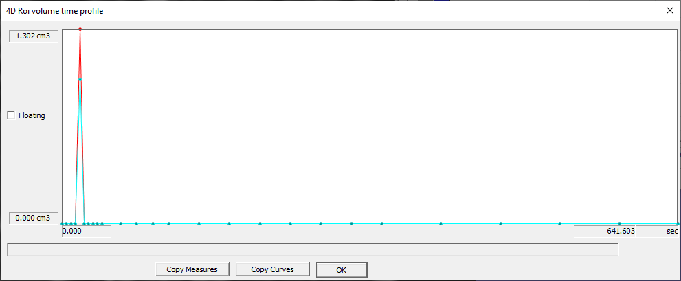
Requires a 4D ROI. Displays info panel (4D ROI volume time profile,
Fig. 13.6).
Shows ROI volume on the vertical axis versus dynamic dimension on the
horizontal axis. Can display multiple curves on the same plot. When the
cursor is placed over a curve, displays ROI parameters: volume, MaxVol
(cm3), FEV1 (cm3), FVC (cm3), FEV1/FVC. Copy Measures copies these
values to clipboard. Copy Curves copies to clipboard ROI volumes as
columns labeled by ROI name (only volumes are included, not the dynamic
dimension). ADD DETAILS.
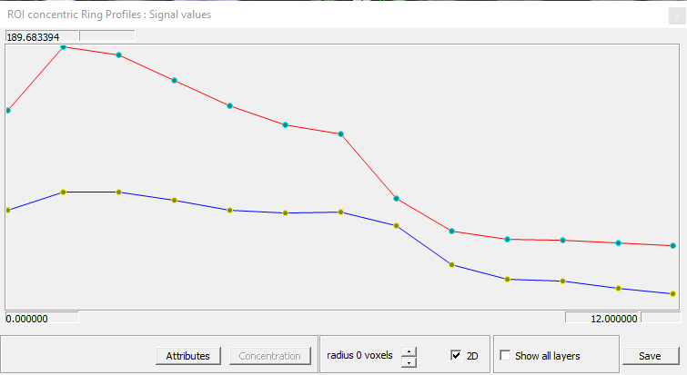
Requires a 3D ROI. Opens dialog panel (Specify Integer). Returns
info panel (ROI concentric ring profiles, Fig. 13.7).
Ring profiles shows plots of signal values versus the ring number
from the outermost to the innermost. ADD DETAILS.
Requires a 3D ROI (visible). Finds the slice with the largest ROI area
and displays it at the maximum zoom that fits into the document window
at its current size. If the active ROI is invisible, shows the visible
ROI. If the active layer is invisible, but there are several visible
ROIs, shows a warning about ambiguous layer configuration.