FireVoxel document windows may contain multiple image layers, similarly
to PhotoShop and similar image processing software. Layers are images of
the same matrix dimensions and resolution (voxel size) overlaid on top
of each other. Layers may be created by the user or by FireVoxel
commands. Layers can be manipulated and transformed using various
commands, moved between compatible documents (of the same resolution and
matrix size), and exported to external files.
A document may contain different types of layers in various
combinations. There is no (practical) limit on the number of layers,
although with many high-resolution layers in the same document,
processing may become slow.
Image layers contain 3D or 4D images created by medical imaging
acquisitions. These images typically consist of voxels stored as 16-bit
integers displayed as grayscale levels.
ROI layers (segmentation masks) are 3D or 4D images with binary values:
filled within selected areas and empty elsewhere. The empty voxels
are always transparent. The filled voxels have a uniform color and their
opacity is set by the alpha value.
Note:
In FireVoxel status bar in the lower left corner,
for ROI layers, the current voxel value is shown as either ON or OFF.
When the cursor is positioned over a filled ROI voxel,
the status bar reads ROI=ON. When the cursor points to
an empty ROI voxel, the status bar reads ROI=OFF
(see an example in Fig. 4.2 showing
ROI=OFF at the current cursor position over the ROI layer
named left_kidney).
Results of arithmetic operations on images and parametric maps reside in
real-valued data layers that are displayed in pseudocolor (color map).
Their opacity is set by the alpha value.
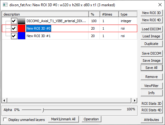
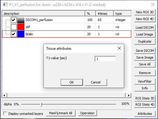
The Layer Control dialog displays the layers in the document and their
properties and allows the user to manipulate them with an array of
command (Fig. 11.1).
To open Layer Control, double-click anywhere on the document window.
Layer Control is accessible only when there are images
open in FireVoxel. The dialog can be positioned anywhere on the screen,
over the FireVoxel main window or outside. If several document windows
are open, the Layer Control shows the layers in the active window;
clicking on another window makes the Layer Control display the layers
in that window. The Layer Control dialog can remain open while the user
is working with several documents and switching from one document to another.
The title bar of the Layer Control panel displays the name of the active
document window and the name and matrix dimensions of the active layer,
as well as the total number of visible layers
(in Fig. 11.1, the active layer matrix is
320 x 260 x 80 x 1 and the document contains 3 layers).
Layer Control displays the layers as a table, in which each
row contains a layer and columns contain layer properties.
Each layer is identified by its name. By default, image layers are named
after the source images. ROI layers are named depending on the command
that was used to create them (e.g., New ROI 3D creates layers named
New ROI 3D #n, n=0, 1, 2…). To rename the layer, double-click its
name, enter a new name in the text box that opens, and click OK.
Layer Control displays the list of layers ordered from the deepest (base
layer) at the top to the shallowest (closest to the viewer) at the
bottom of the list. New layers are appended at the bottom of the
list (that is, overlaid on top of the already existing layers). To
reorder layers, click the layer name and drag it up or down on the
list.
The active layer highlighted in the Layer Control by a red border. The
active layer can be manipulated and will be the one manipulated by
default (e.g., ROI drawing will be done on the active layer). Many
FireVoxel commands by default act on the active layer. To activate a
layer, click on its name. If an action creates a new layer in a
document, this new layer becomes active by default.
11.2.5. Layer visibility and Display Unmarked Layers
A check box in front of the layer name toggles the visibility of this
layer. Unchecked layers become invisible. However, they can be made
visible by checking Display Unmarked Layers box.
A small square swatch next to the layer name shows the color map or ROI
color. Color map are selected for acquired images or parametric maps.
The ROI layer color is assigned by default when the ROI layer is
created. The color map and the ROI color can be adjusted using
ViewFilter option on the right hand side of the panel.
The first column after the layer name, labeled %, shows the layer’s opacity,
expressed in percent, from fully transparent (0%) to fully opaque (100%).
The Alpha slider under the layer list in the Layer Control allows
the user to change the opacity of the active layer.
Note that although alpha expresses opacity, it is commonly used interchangeably with
the layer transparency, which is (100% - Alpha).
By default, image layers are shown as 100% opaque and ROI layers as 20% opaque
(note these values for the base layer and two ROI layers shown
in Fig. 11.1).
To change the layer transparency, make the layer active by clicking its name
in the Layer Control, then click and drag the alpha slider to the left
(towards 0%) to make the layer more transparent or to the right (towards 100%)
to make the layer less transparent. Click on the slide to the left or right
of the slider to chang the opacity in 20% increments in either side.
Note:
Transparency (or Alpha) is an attribute of the entire volume layer,
with a single value for the entire layer. Transparency affects only
how the image is displayed and does not affect any image processing operations.
VOID (value) is an attribute of an individual voxel, which enters
into image processing operations. All VOID voxels are always displayed as
fully transparent, regardless of the layer’s transparency setting.
The column labeled #times contains the number of dynamic frames in
the layer. For 3D volumes, #times=1. For 4D images and ROIs,
#times=number of frames.
The column labeled type shows the data type in the layer. Images are
usually integer, parametric maps and other calculated layers are often
real, ROI layers are labeled roi (binary images with voxels filled
with 1s and 0s, with 0s fully transparent and 1s opacity given by the
alpha value).
Create a new 3D ROI layer, which is appended at the bottom of the list
of layers. The new ROI layer is named New ROI 3D #n, n=0, 1, 2… The
color is assigned automatically from a sequence (red, blue, green,
yellow, cyan, brown, etc.)
Create a new 4D ROI layer, appended at the bottom of the list and
labeled New ROI 4D #n, n=0, 1, 2… The ROI size in the 4th
(dynamic) dimension will be the same as the size of the base image.
Opens browse for folder dialog to select a directory with DICOM
documents. Once the folder is selected, the DICOM Tree panel is opened,
as in File > Open DICOM command. Only DICOM documents with the
same matrix size and resolution can be opened as a new layer. If the
dimensions are incompatible, after the user clicks Load, a warning
is displayed (Equal dimensions are expected) and loading files is
canceled (Failed to add a new layer). If the images are compatible,
Load adds them as a new layer and makes this layer active. The name
of this layer will be the same as the name of the loaded DICOM images.
Opens browse for file dialog allowing the user to select an image file
in one of the compatible formats. The image is added as a new layer,
named as the loaded file, which is made the active layer.
Duplicate the active layer. The new layer is added at the bottom of the
list and named as the active layer with added _copy suffix. Both
image layers and ROI layers can be duplicated.
Save Image saves the active layer as NIfTI image (.nii).
Saving in older MIDAS (.im) or ANALYZE (.img) formats is also possible,
but less preferred because of these formats’ limited ability to store
image orientation unambiguously. Save All saves each visible layer
in the document as a separate image. The command opens a file-save dialog
with -.nii appearing by default in the File name box. When the user
clicks Save, each of the layers is saved as an image of the same name.
Removes unmarked (unchecked) layers after asking the user to confirm
this action (Remove all unmarked layers?). If all layers are
checked, removes the active layer, also after user’s confirmation
(Remove Active Layer?).
Opens display options depending on the layer type:
For image layers (integer or real valued): grayscale or color map selection panel;
For ROI layers: color picker panel.
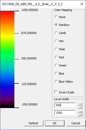
For image layers, Color Mapping radio buttons can be used to select
gray scale (Color Mapping: None) or one of eight available color maps
(Fig. 11.2).
The corresponding color bar is shown on the left, with numbers indicating
upper and lower limits, center, as well as the first and third quartiles.
Checking Invert Scale check box reverses the order of the colors between
the upper and lower limits.
The Level-Width text boxes show values of the window level
(color scale center) and width (the range between the lower and upper limits).
The window level and width values can be changed by entering new numbers
into the respective boxes or by using the up and down arrows next to the text boxes,
with the changes taking effect instantly. Clicking Default restores the default
values of level and width.
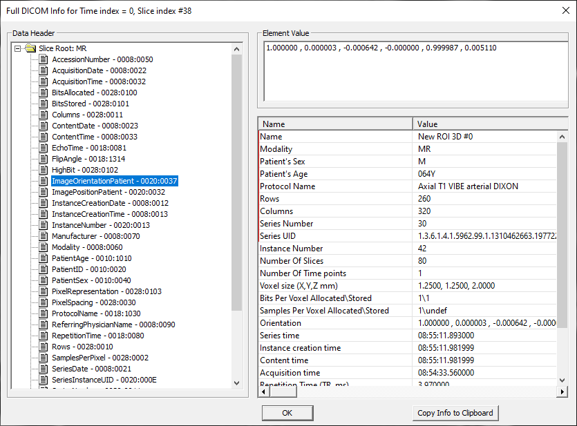
Opens Full DICOM Info panel with header information for the selected layer
(Fig. 11.3).
The panel consists of 3 parts: Data Header, Element Value, and
selected tags. Data Header part shows a list of header tags. Clicking
each tag shows its value in the Element Value window. The selected tags
part shows image properties: Name, modality, rows, columns, etc.
Clicking Copy Info to Clipboard copies the information from the
selected tags panel that can be then pasted into a text file and saved.
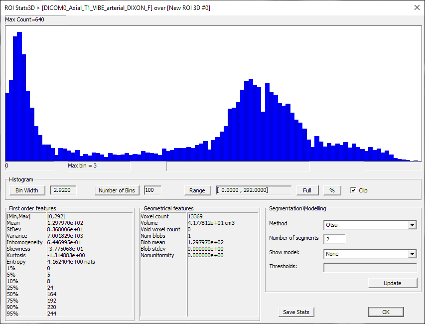
Opens ROI Stats 3D dialog with the image statistics (Fig. 11.4).
If the active layer contains an image (integer- or real-valued),
the statistics are displayed for the voxel values in this layer.
If the document also contains a single visible ROI, the statistics are shown
for the part of the image within this ROI. If the document contains
no visible ROI or multiple ROIs, statistics are shown for the entire image.
If the active layer is an ROI, the statistics are displayed for the only visible
image layer. If multiple image layers are present, an error message is shown
(Ambiguous Layer Configuration). If only ROI layers are visible, the statistics
will show a constant voxel value of 1.
The ROI Stats 3D dialog includes the following features:
Histogram – A bar plot of the distribution of voxel values in
the active layer (and within the ROI, if applicable) and histogram controls.
Controls include checkboxes and buttons that open subdialogs for
entering values.
Histogram Controls – Bin Width, Number of Bins (N_Bins), Range ([Min, Max]).
Bin Width = (Max – Min)/N_ Bins
By default, the Range is set to the full range of voxel values between
the minimum and maximum values. The default number of bins is 100.
The default Bin Width = Range/100.
For a fixed Range, the Bin Width and Number of Bins are automatically
adjusted when either of these values is changed. That is, if the Number of Bins
is changed, the Bin Width is adjusted accordingly. If the Bin Width is changed,
the Number of Bins is adjusted.
When the Range is changed, the Bin Width remains fixed, but the Number
of Bins is automatically adjusted.
Full – Sets the Range to the to full interval between the minimum
and maximum voxel values (while the Bin Width remains fixed and the Number
of Bins is adjusted).
Clip – (Checked by default) If checked, only the values inside the Range
are used to display the histogram and calculate statistical parameters, and
the edge bins at Min and Max ends of the Range are excluded.
The number of voxels included is shown in Geometrical features > Voxel count.
Toggling Clip on and off changes the Voxel count (unless Range is set to Full
- then Clip has no effect).
If Clip is unchecked, the edge bins are included, and all voxel values are
displayed in the histogram and used for the statistics calculations.
The Voxel count reflects the total number of voxels in the ROI (or image).
The user is advised to pay close attention to the Clip setting because it may
affect the output of the statistical analysis.
Percent (%) – Sets the Range by specifying the range between the Low
and High voxel percentiles in the image (see First order features).
By default, Percent is set to the full range from Low=0% to High=100%.
When Percent is set to any other values, the Range is recalculated,
the Bin Width remains fixed, and the the Number of Bins
is adjusted. When Percent is clicked again, the default Low and High percentiles
are set to 0% and 100%, respectively (i.e., the previous settings are
not retained).
First order features – Range and first-order moments of voxel
value distribution:
[Min, Max] – Minimum and maximum voxel signal values Mean – Mean signal over all voxels (within image or ROI) StDev – Standard deviation over all voxels (within image or ROI) Variance – Expected value of squared deviation from the mean Inhomogeneity = StDev/Mean – Coefficient of variation Skewness – Measure of asymmetry about the mean Kurtosis – Measure of “tailedness” of the distribution in relation to
a normal distribution. Distribution with high kurtosis have heavy tails.
Distributions with low kurtosis have light tails. Entropy – Measure of uncertainty in the variable’s outcomes. Percentiles (1, 5, 10, 25, 50, 75, 90, 95, 99%) –
Values of the displayed variable, at or below which a given percentage
of voxels falls.
Example (Fig. 11.4): If 75% percentile is 192,
75% of voxels have signal less than or equal to 192.
Geometrical features – Size and other geometrical characteristics
of the image or ROI:
Voxel count – The number of voxels within an image or ROI
Volume – Volume of image or ROI (in cm3)
Void voxel count – Number of VOID voxels
Num blobs - Number of unconnected subregions
Blob mean – Mean over unconnected subregions (equal to the mean value in
First order features if the image or ROI contains a single region)
Blob stdev – StDev over subregions
Nonuniformity – Measure of variation across subregions.
Segmentation\Modeling – Options to identify segments within the
distribution. Used for segmentation of ROIs into subregions.
ADD DETAILS
Method – Dropdown menu with a choice of methods (Default: Otsu, Zigalga,
Bimodal Gauss with Ratio, Bimodal Laplace with Ratio, Bimodal Gauss PVV,
Bimodal Laplace PVV, Air Threshold)
Number of segments
Show model – None, All Curves, Cumulative
Thresholds
Update – Recalculate and display results
Save Stats – Create RoiStats3D.txt file with summary statistics
with the current settings. By default, when this file is created, it is saved
in FireVoxel’s Temp folder. If the user changes the histogram settings and clicks
Save Stats again, another RoiStats3D.txt file will be created and opened.
The previously created file will be overwritten without a warning.
The user is advised to save the statistical results in a different directory
and label these files systematically for future reference.
ROI stats include: Volume (in voxels and cm3), Signal Min, Max, Mean, Median,
Stdev, Inhomogeneity (stdev/mean). Also included are Histogram stats and histogram
values (Bin/Signal/Count) and parameters (skewness, kurtosis, entropy).
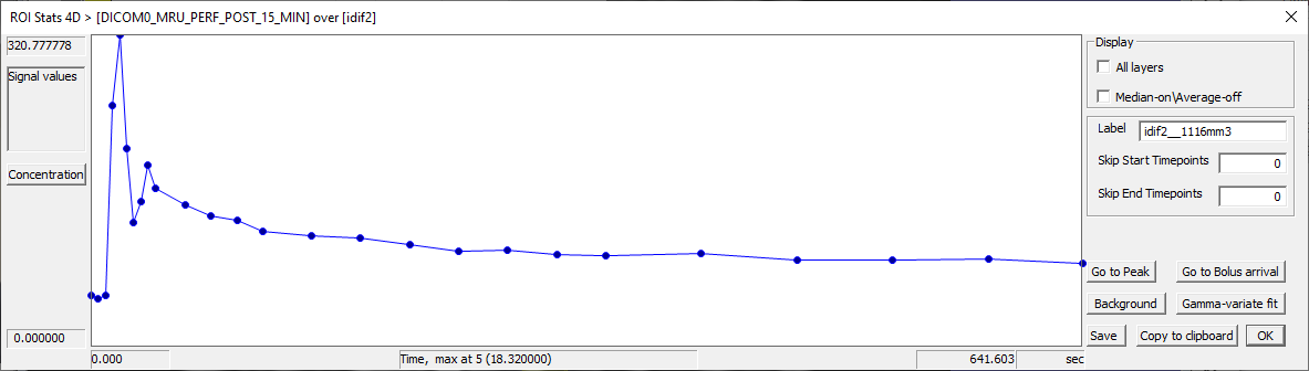
Opens ROI Stats 4D panel for a dynamic experiment (Fig. 11.5).
The left side of the panel displays the plot of the average values
within the ROI versus the dynamic dimension
(time, b-value, echo time, etc.). The axes show the
name of the variable plotted and the minimum and maximum values.
The right side of the panel shows display options and commands:
Display:
All layers – Check box allowing to plot values within all visible
ROI layers. Each ROI’s data will be shown in the color of the ROI
layer.
Median-onAverage-off – Displays the median value instead of the
average?
Label – Name of the ROI with the ROI volume in mm3 (e.g.,
ROI1_1000mm3)
Skip Start Timepoints and Skip End Timepoints – Text boxes
allowing entering the number of points to be hidden in the
beginning and end of the dynamic series.
Commands:
Go to Peak – TBA
Go to Bolus Arrival – TBA
Background – Color selector allowing to change the plot background
Gamma-variate fit – Opens Parametric Map calculation for fitting
the curve with a gamma-variate fit (for input functions)
Save – Open file save dialog for saving the plotted curve (time
activity curve) as a text file. The file contains: curve label
(from above), and tab-delimited columns (with column headers) –
dynamic coordinate (e.g., time (sec)), avgVal – average signal
value in the ROI, and vol_cm3.
Copy to clipboard – Copies the same information to clipboard for
pasting into a spreadsheet or another document.
The following operations act on the active layer (layer A)
or on two visible layers, layer A (base layer, furthest from the viewer)
and layer B (top layer, closest to the viewer). To swap operands,
reorder layers in the Layer Control layer list (Layer order and reordering layers).
To use Layer Operations, mark two layers and unmark all other layers,
click Operation and then select the appropriate operation. A new layer
will be created with the result of the operation, labeled [operation]
result (e.g., union result).
If the user selects an operation that does not match the type of
selected layers, an error message will be shown (ROI is required in
this operation for binary operations or ROI is not allowed in this
operation for arithmetic operations). If more than two layers are
selected, an error message will be shown (Invalid number of operands
for this operation). In these cases, the operation will not be
performed and no new layers will be created.
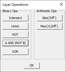
The layer operations are split in two groups, Binary and Arithmetic
operations:
Binary Operations
Operate on one or two ROI layer(s) and return an ROI layer
(Fig. 11.8).
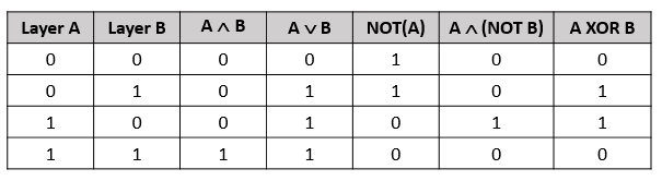
Intersect – A ^ B – A AND B – Returns a layer with voxel values
of 1 where voxels in both layers A and B have the value of 1 and zero otherwise.
The output layer is named intersect result.
Union – A v B – A OR B – Returns a layer with voxel values of 1
where voxels in either or both layers A or B have the value of 1
and zero otherwise (where both A and B have zero values).
The output layer is named union result.
NOT – NOT(A) – Logical complement. Returns a layer
with voxel values of 1 where layer A have zero values and zero elsewhere.
The output layer is named not result.
A AND (NOT B) – Returns a layer with voxel values of 1 where A has the value
of 1 and B is zero and zero otherwise. The output layer is named a_and_not_b result.
XOR – A XOR B – Exclusive OR – Returns an ROI layer with voxel values of 1
where layers A and B have different values and zero where A and B have
the same values. The output layer is named xor result.
Arithmetic Operations
Require two integer- or real-valued image layers and return a single image layer
of the same type as the operands.
Abs(Diff) – |A – B| – Absolute difference – Returns a real-valued
color map layer where each voxel contains the absolute value of difference between
layers A and B. The output layer is named absolute difference result.
Max(0,Diff) – Diff=A–B if A>B and zero otherwise – Zero-truncated difference –
Returns a real-valued color map layer where each voxel is equal to the difference
between layers A and B if this difference is positive (A>B) and zero otherwise.
The output layer is named zero truncate absolute difference result.
To obtain Diff=B–A, swap layers A and B in Layer Control
by dragging and dropping the layer names into appropriate positions
so that layer B is located higher on the layer list than layer A.
The Layer Control dialog can be used to copy layers between compatible
documents, i.e., document windows that display images with the same matrix
dimensions and voxel size. To copy a layer from Document 1 to Document 2,
open both documents in FireVoxel in two different document
windows, open Layer Control, and click anywhere on Document 1 to activate it.
Next, in the Layer Control dialog, click the layer that needs to be copied,
drag it anywhere over Document 2 and drop it.
To verify that the layer has been copied, click on the Document 2 window
and inspect the list of layers in the Layer Control. The copied layer
should be added at the bottom of the list.
All types of layers can be copied using this method, but only between
compatible documents.
As an alternative to this method, layers can be copied by saving them
as images and loading them into the target document. To use this method,
click Document 1, activate the layer to be copied in Layer Control and
save it using Save Image, for example, in NIfTI format (.nii).
Next, click Document 2, and use Load Image
in Layer Control to select the just saved image. The loaded image
will be added to the bottom of the list of layers. The name of this new layer
will be identical to the name of the file, including the .nii extension.