The Trace tab offers commands for accessing the Magnetic Trace
(MagTrace) tool for defining vector contours that snap to edges of
objects in the image. This tool can be used to speed up manual
segmentation of organs and tissues.
When using the Magnetic Tool, the user places clicks the mouse
along the edge of the organ to be segmented to place control points
connected by a spline curve (Fig. 18.1).
The “magnetic” property allows placing the control points
in the vicinity of the edge, but not exactly on it, and the Magnetic
Trace tool automatically moves them closer to the edge. The user can
configure the MagTrace properties and control the precision of snapping.
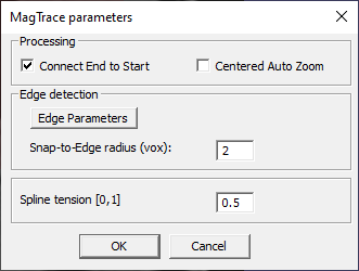
The MagTrace tool can be configured before use by selecting Trace >
MagTrace settings. This command opens a panel with the tool
parameters (MagTrace Parameters, Fig. 18.2).
Connect End to Start – Creates a closed contour. Checked
by default.
Centered Auto Zoom – Unchecked by default. ADD DETAILS.
Snap-to-Edge radius (vox) – The radius of the MagTrace tool aperture
(in voxels) within which the tool detects edges and snaps to them. The
larger the aperture, the faster the contour can be drawn, but also the
more likely the tool is to snap to irrelevant edges. The smaller the
aperture, the slower and the more precise is the drawing.
Spline tension [0, 1] – A coefficient that controls the curvature of
the spline connecting the control points. The lower the tension, the
straighter the line. A straight line has the spline tension of zero. The
tension can also be adjusted after the contour is drawn through the
contour properties panel.
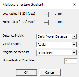
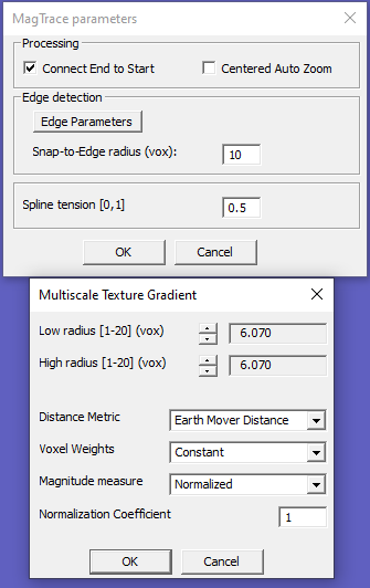
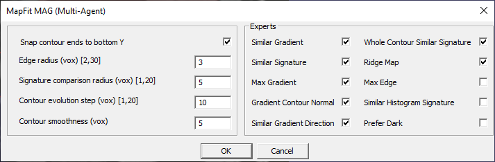
Edge Parameters – Opens a secondary dialog (Multiscale Texture Gradient,
Fig. 18.3) to adjust the parameters of edge
detector algorithm. These parameters may be adjusted for specific tasks
and image types. Optimal presets configured for commonly used applications
are available through Trace > Application Specific Settings.
See Volume > Multiscale Texture Gradient
for details of this dialog and Texture Edge Detection.
Starts the MagTrace tool. MagTrace can also launched
using the main toolbar icon .
Once MagTrace is launched, the cursor becomes a green circle.
The size of this circle is set by
Snap-to-Edge radius.
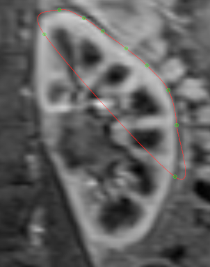
To draw a contour, click the image to place the control points. The
points will be shown as green circles connected to the previous point
with a red line (spline).
The contours are defined only on the current slice. To replicate the
contours (to the current slice or other slices), use Copy commands.
The radius of the snapping region can also be controlled by scrolling
the mouse wheel up and down.
If there is an active contour in the document, starting MagTrace will
continue drawing this contour. To start drawing a new contour, press Esc
to exit MagTrace, click anywhere on the image to deactivate the first contour,
then start the MagTrace tool again and draw the second contour.
To exit from the MagTrace tool, press Esc.
To delete a contour, click on it to activate (green control points appear)
and then press Delete.
To manipulate the individual commands, press Esc exit the MagTrace tool.
Click the contour to activate it. An active contour shows the control
points as green circles(Fig. 18.6).
Fig. 18.6 Active MagTrace contour shows control points.
To move a control point, hover the cursor over it (the cursor
becomes a cross), click and drag it to a new location and then release
the mouse.
To add a control point, hover the cursor over the spline contour
(the cursor becomes a cross), and press Alt+1.
To delete a control point, hover the cursor over the point to be
deleted and press Alt+4.
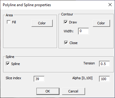
The properties of an existing spline can be configured when the MagTrace
tool is off. Double-click the contour to open Polyline and Spline
properties (Fig. 18.7).
Alternatively, select View > Contour and Fill Properties
to open this panel.
The options include:
Area –- Click the Fill box to fill the area within the
contour. Press the Color button to open the color selector to
customize the color.
Contour –- Check the Draw box to show the outline of the contour.
Click the Color button to open a color picker and select the line
color. To control the line width, enter a number (in points) in
Width box. Check the Close box to connect the first and last
points in the contour.
Spline –- Check the Spline box to convert the contour into a
spline. Uncheck for straight line. If Spline is checked, enter the
spline tension into the Tension box.
Slice index –- Displays the slice number (first slice has the index
of 0) on which the contour is defined. Enter another number in the
Slice index box to move the contour to that slice.
Alpha [0, 100] –- Value of the alpha channel, in percent, controlling
transparency of the contour. Transparency of both the line and the fill
area (if selected) transparency is set simultaneously. Alpha equal to
zero results in a fully transparent contour, alpha of 100% results in a
fully opaque contour.
Fig. 18.7 MagTrace Spline and Polyline properties.
Copy selected spline (Alt+5) – Copies and pastes the active contour
onto the current slice. If the current slice is the slice containing the
selected contour, the contour is duplicated in place. The pasted contour
is pasted with the default parameters (color, fill, close, alpha).
Snap selected spline to image (Any direction: Alt+2) – Snaps the
selected spline to the edges of the image (in plane and across slices).
ADD DETAILS
Snap selected spline to image (Normal: Alt+3) – Snaps the selected
spline to the edges of the image (across slices). ADD DETAILS
Copy from adjacent slice and snap – Combines copy and snap commands.
Copies and pastes the selected slice to the current slice and snaps the
contour to images. May be useful when replicating an outline of an organ
through slices.
Use Vector > Rasterize selected vector entities or Rasterize
All Splines to rasterize the active spline or all spline contours in
the document. The raster ROIs are placed either into the current ROI
layer or a new ROI layer, if the current layer is not an ROI layer.
See Vector chapter for details.