VROIs are defined by the coordinates of their corners in
contrast to raster ROIs, which are defined as arrays of pixel values.
VROIs are used for annotating subsets of the document, cropping images,
measuring distances, placing anatomical landmarks, and as seeds required
by several commands (Connected Component by Seed, EdgeWave segmentation,
Image-Derived Input Function).
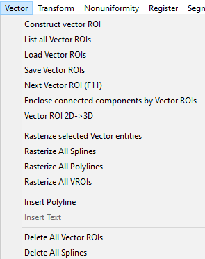
VROIs can be created and manipulated using the commands under the main menu’s
Vector tab (Fig. 14.1), which becomes available when images are
loaded into FireVoxel. VROIs can also be drawn and rasterized with the help
of the Toolbar tools.
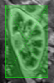
VROIs are shown as semi-transparent rectangles, with sides parallel to
the (X,Y,Z) axes of the document (Fig. 14.2). The two intersecting
diagonals indicate the VROI center. The size of a VROI may be smaller than
a single voxel. As a result, a VROI may be nearly invisible.
The visibility of all vector entities (VROIs, polylines, and contours)
in a document can be toggled on and off using View >
Display/Hide Vector.
Navigate to the slice, or view (if multiple orthogonal projections are open),
or a frame in a 4D (dynamic) document on which VROI will be drawn. VROIs can
be drawn in either the Slice or the Film view. However, a VROI is initially
defined only on a single slice (2D) and only on the current dynamic frame
in a 4D dataset.
Select Vector > Construct Vector ROI (or click Construct
vector ROI toolbar icon ). The cursor will become a cross.
Move the cursor to the location where the lower left corner of the VROI
should be and left-click (the mouse button does not need to be held down
after the click). A pair of small green circles (handles) will appear at
the location of the mouse click. Move the cursor towards the upper rightcorner of the VROI. The VROI will be shown as a semi-transparent green
rectangle with the corners at the initial mouse click and the current cursor
position. Click again to complete the VROI. The cursor will revert to
the standard white arrow.
To exit from the VROI tool without drawing a VROI, press Esc.
The dimensions and position of the VROI can be easily adjusted, therefore
it is not critical to draw VROIs precisely on the first attempt.
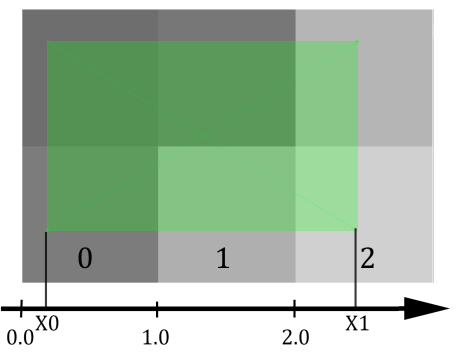
Fig. 14.3 VROI (green) coordinates and voxel indices.
A VROI is defined by the coordinates of its handles:
the lower left corner (X0, Y0, Z0) and the upper right corner (X1, Y1, Z1).
The VROI coordinates and dimensions are specified as real (decimal)
numbers. This leads to the need to map the real-valued VROI coordinates
to integer voxel indices, which take integer values (0, 1, 2,…).
In FireVoxel, voxel i contains points whose coordinates lie in
a semi-open interval [i, i +1) (closed on the left, open on the
right). Therefore, voxel 0 extends over the coordinates [0.0, 1.0):
coordinate 0.0 is part of the first voxel, whereas the point with
coordinate 1.0 is part of the second voxel (Fig. 14.3).
This convention holds for each of the {X,Y,Z} axes.
A VROI also has a dynamic index (4th dimension coordinate).
Dynamic index takes integer values in the interval [t0, t1], where t0 and t1
are the first and last indices of the dynamic frames on which the VROI is defined.
A VROI has two states, active and inactive. An active VROI can be manipulated
(moved, resized, rasterized, etc.). An active VROI shows handles small circles
in the lower left and upper right corners. Inactive VROIs do not have these handles.
Only one VROI in the document can be active at a time.
To activate a VROI, click anywhere inside this VROI. To inactivate a VROI, click
anywhere outside the active VROI. To resize a VROI, activate it, left-click
one of its handles (the cursor will become a cross), then hold and drag it
to increase or decrease the size of the VROI.
To move a VROI without changing its dimensions, right-click an active VROI
(the cursor will change to four white arrows), then hold and drag it to a new location;
release the right mouse button to finish.
A 2D VROI can be manually converted into a 3D VROI by displaying the image in
orthogonal projections (click Display Orthogonal Projections toolbar icon
) and resizing the VROI to extend across several slices.
Alternatively, this can be done using Vector > Vector ROI 2D -> 3D.
The dimensions, position, and other features of VROIs may also be configured using
the Vector ROI Properties panel.
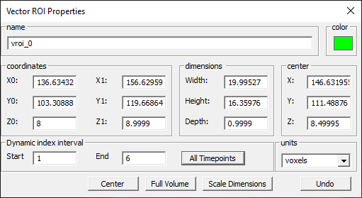
VROIs can be adjusted and manipulated via the Vector ROI Properties panel
(Fig. 14.4). To open it, double left-click on the VROI.
A common mistake is to double right-click, which switches the document from
the Slice view to the Film view. To recover from this mistake, navigate to
the VROI and double right-click again to switch back to the Slice view.
The properties panel can remain open while the user activates different VROIs,
uses Vector > Next Vector ROI (F11) function, or even deletes all VROIs.
The Vector ROI Properties panel has the following fields.
Name - Text box containing VROI name. By default, VROIs are named vroi_N
(N=0, 1, 2,…) and numbered in the order in which they are created in the document.
Custom VROI names may be entered into the name box. Renaming will not affect
their original order, which is used, e.g., by Vector > Next VROI (F11)
command.
Color - The color swatch showing the current color (green by default).
Double-click to open the standard Windows color picker and select custom color.
The color may be changed only for already existing VROIs.
Coordinates - The real-valued coordinates of the lower left and upper right corners,
(X0, Y0, Z0) and (X1, Y1, Z1), respectively. By default, the units are voxels, but
may be switched to millimeters by using the dropdown menu labeled units (in the lower
right corner) and selecting mm instead. The coordinates are recomputed when VROI
is moved or resized manually.
Typing over the current values will change the position and dimensions of the VROI.
After typing a number in a text box, click on another text box or press
Tab for the change to take effect. Pressing Enter would close the properties panel.
Units - Drop-down menu to select the units of Coordinates, Dimensions, and Center
(voxels (default) or millimeters).
Dimensions and Center - Dimensions (DX, DY, DZ) are labeled width, height,
and depth, respectively. Center specifies the (CX, CY, CZ) coordinates of the
VROI center (indicated by intersecting diagonals). These values are
recomputed dynamically when VROI coordinates are changed:
Typing new values into these boxes will change the size of the VROI.
The coordinates will be recomputed accordingly. To extend a VROI over several
slices, enter a number greater than 1 into the Depth box.
When D or C values are modified, the corresponding minimum and maximum values are
recomputed:
Dynamic index interval - The first and last dynamic frames [t0, t1] between
which VROI is extended. By default, in a 4D dataset, VROI is defined only
on the current dynamic frame. Type new values into the boxes to define a custom interval.
Scroll through dynamic variable (using right and left arrow keyboard keys)
to ensure that the VROI has been extended correctly.
All Timepoints – Clicking this button extends the VROI to all dynamic
frames in a 4D dataset (for any dynamic variable, including time, b-value,
flip angle, inversion time, etc.). It is equivalent to setting dynamic index interval
to t0=1 and t1=N, where N is the total number of frames in the dataset.
Center, Full Volume, Scale Dimensions - Functions for quick positioning or scaling.
Center moves the VROI so that its center coincides with the center of the image.
Full Volume extends the VROI to the entire image volume on all slices
of the current dynamic frame (use Dynamic index interval settings to extend
to other frames).
Scale Dimensions opens a dialog to enter a scaling factor by which all three
VROI dimensions will be multiplied after the user clicks OK (default, 1, no scaling):
DX’ = DX * scale, DY’ = DY * scale, DZ’ = DZ * scale. Scaling resizes the VROI,
but does not change the in-plane coordinates of its center.
the total number of VROIs followed by a list of VROI names and the intervals
of dynamic indices on which each VROI is defined.
Opens dialog with the total number of VROIs in the document and a list of VROIs.
For each VROI, the dialog shows the VROI’s name and [t0, t1] - the interval of
dynamic indices for which the VROI is defined. The VROIs are listed in the order
of their creation in the document (the same order is followed by
Next VROI (F11)).
The command lists the VROIs regardless of the visibility option
set by View > Display/Hide VROI.
Saves all vector ROIs in a file with .vroi extension.
Opens a file-save dialog to select the directory and name of the target file,
which is given a .vroi extension. This file can be opened using a text editor,
such as Notepad. The .vroi file contains the total number of ROIs followed
by each VROI’s defining properties (ROI label, Windows color code, t0 and t1
dynamic indices, X0, X1, Y0, Y1, Z0, Z1 coordinates).
Note that saving the entire document in the FireVoxel .fvx format also
retains all VROIs.
Opens a browse-for-file dialog to select a .vroi file.
Once the user selects this file, the VROIs are recreated in the document
and displayed. If these imported VROis are then modified (resized, repositioned,
etc.), they need to be saved again, either with the document or as a .vroi file.
Note that the command does not check whether the loaded VROIs match
the current document, or if they are already present in the document.
If these VROIs are already present in the document, the newly loaded VROIs
will be displayed on top of the existing ones.
Duplicate VROIs can be visually identified by their higher opacity
and also by using List all VROIs.
Activates the next VROI (in the order they were created) and display
the slice containing its center (note that voxel coordinates, including
slice numbers, start from zero). If the document is in the Film view,
the command switches it to the Slice view. If the active VROI is the last
one in the document, the command circles back to the first VROI.
This command is convenient when multiple, overlapping VROIs are present
in the document.
Creates a new VROI around each connected component in the active ROI
layer. A message shows the number of VROIs created. If the command is
repeated (without any changes made to the raster ROIs or VROIs), no new
VROIs are created. If either the VROI or the raster layer have been
modified, the command creates a new VROI.
A VROI can be rasterized, or used to create a raster ROI
covering the area enclosed by the VROI.
Rasterize selected Vector entities rasterizes the active VROI, polyline,
or spline (contour). The same operation can be performed by clicking
toolbar icon.
Rasterize All Splines rasterizes all splines (contours) with three or more
points. The contours may be created by Magnetic Trace or
Insert polyline commands.
Rasterize All Polylines rasterizes all polylines with three or more points
(two or more lines).
Rasterize All VROIs rasterizes all VROIs in the document.
The results of the Rasterize commands are added to the active ROI layer.
Open the Layer Control panel (by double left-clicking on the image) to view
the document layers. If the active layer is not an ROI layer, a new ROI layer
is created automatically, and rasterized areas are added to this new layer.
To add the rasterized area to a specific ROI layer, activate this layer first
by clicking on its name in the Layer Control, and then apply the Rasterize command.
Launches the polyline drawing tool.
Clicking toolbar icon launches the same tool.
Click the image to place control points connected by straight lines.
Press Esc to exit the tool.
Active polylines show green control points, like other vector entities.
Click the polyline to activate it. Click away from the polyline to de-activate.
Active polylines can be manipulated.
Click and drag individual control points to move and reshape the polyline.
Right-click and drag any location on the polyline to move the entire polyline
to a new location.
Active polyline can be deleted by pressing Delete.
For a two-point vector, the direction is indicated by an arrow
at the end of the vector. The length (in millimeters) is also shown
in red next to the vector before the second point is placed.
To display the length at all times,
use View > Display\Hide Curve Length.
For a three-point sector, the direction is indicated as a green arc
with an arrow (from the first segment towards the second segment).
The angle measure (in degrees) is shown in green next to the apex of the angle.
To display the angle at all times,
use View > Display\Hide Curve Length.
The properties of the active polyline can be adjusted by double-clicking
the polyline or selecting
View > Contour and Fill Properties
to open Polyline and Spline properties. The panel allows the user
to control the fill, line, and transparency properties, and also
convert the polyline into a spline.
Delete All VROIs - Deletes all VROIs in the active document.
Polylines and splines are unaffected. The active VROI can be deleted by pressing Delete.
The active VROI will be deleted even if it is not visible.
Delete All Splines - Deletes all splines (contours).
VROIs or polylines are unaffected.
 ). The cursor will become a cross.