FireVoxel offers users a variety of tools for manual and automatic
segmentation of 3D images.
Manual segmentation of 3D images can be performed using a combination of
the Paintbrush tool, ROI commands (see ROI), and Magnetic Trace (see Trace).
However, manual segmentation can be time-consuming and prone
to observer bias.
Automatic segmentation can be performed using commands based on
the EdgeWave algorithm that are offered under Segment menu tab.
These commands include options for various segmentation scenarios,
as well as pre-configured workflows for brain segmentation,
which combine non-uniformity correction based on the N3 method
and EdgeWave segmentation.
EdgeWave is an automatic segmentation algorithm for 3D medical images
based mainly on the shape characteristics of an image, as it uses
primarily thresholding and morphology operations.
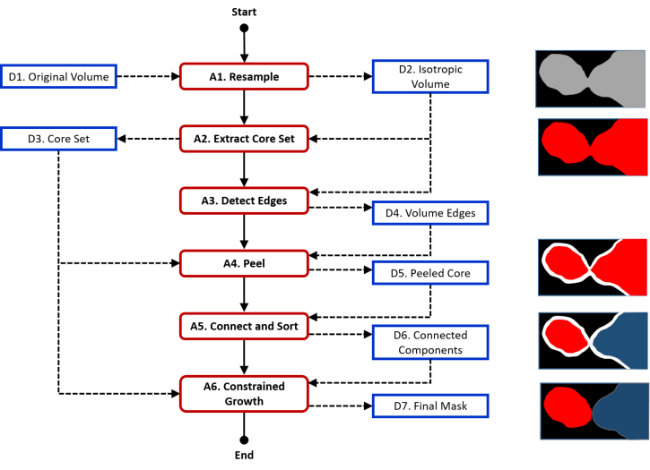
The EdgeWave algorithm follows the following main internal steps
(Fig. 24.1).
Fig. 24.1 EdgeWave algorithm diagram with the output of each step
shown schematically on the right (black - background,
gray - tissue, red - core set & final mask,
white - peeled voxels, blue - part of core set excluded from
final mask).
Step 1 - The original image is resampled.
Step 2 - Thresholding by image intensity is applied
to roughly delineate the region that needs to be segmented,
which we will call the Core Set. The Core Set must enclose
the segmentation target, otherwise the segmentation will fail.
Step 3 - Edge detection is then applied in some cases.
Edges are areas of the Core Set where image intensity changes abruptly.
Step 4 - The boundary of the Core Set is eroded, or peeled.
The Peel operation removes all voxels within a certain distance from
the boundary using rules applied to each voxel and its neighbors.
Peeling enlarges the gaps between different regions of the image,
removes small details, and breaks “bridges” between weakly
connected areas. The thickness of the region to be removed is
controlled by the peel distance, measured in voxels or millimeters.
Step 5 - The algorithm breaks up the peeled Core Set into blobs,
or connected components. It then determines which connected components
are to be retained and which ones should be discarded.
Step 6 - The selected connected components are subjected
to constrained growth, or dilation. The Grow operation adds voxels within
a given distance of the ROI boundary. Any recovered voxels must still belong
to the Core Set. The thickness of the recovered region is controlled by
the grow distance, which should be larger than the peel distance.
Selecting Segment > EdgeWave Basic or using
icon on the main toolbar opens the EdgeWave dialog panel that
allows the user to customize the tool by selecting appropriate
parameters (Fig. 24.2).
Basic EdgeWave tool can be used in two scenarios, depending
on how the connected component is determined:
1) with the seed (vector ROI) or
2) without the seed.
If the seed option is used, prior to running EdgeWave, the user
needs to draw the seed in an area of uniform tissue to be segmented.
For example, in brain segmentation, the seed is usually placed
in white matter.
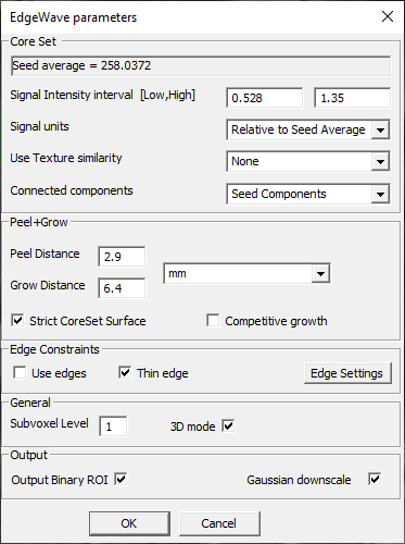
Fig. 24.2 EdgeWave dialog (configured with vector ROI seed).
Core Set parameters:
[Seed average signal box] – If a vector ROI is present
in the document, this box shows the average signal intensity
Savg within this ROI. WHAT IF SEVERAL VROIS?
Signal Intensity interval [Low, High] and Signal units –
The lower and upper limits of the signal intensity (SI) interval,
specified, as indicated by Signal units drop-down menu, as either
1) Absolute SI - absolute signal intensity, or
2) Relative to Seed Average, as a fraction of the average
signal intensity Savg. By default, the interval
is [0.528,1.35]*Savg (typical range for white matter
segmentation on T1-weighted brain images).
Connected components – Drop-down menu with options of selecting:
All components,
Max components only - maximum connected component, or
Seed components – connected component determined starting
from the seed, if the vector ROI seed is present,
by the region-growing method.
Peel+Grow parameters:
Peel Distance and Grow Distance – Thickness of the region
to be removed (for Peel) or added (for Grow)
[Peel/Grow Distance units] – Drop-down menu to select
millimeters or voxels as units of peel/grow distance.
Opens the EdgeWave dialog that can be configured
in the most general scenario, with and without a seed.
See EdgeWave Dialog for parameter details.
The command creates a new layer with the segmentation mask.
The vector ROI seed is NOT deleted after segmentation.
24.2.4. EdgeWave-Live with Single Seed and Constraint ROI
Expects isotropic volume (T1 MPRAGE?).
Requires a raster ROI to be drawn around the organ to be segmented
(Core Set). This ROI must enclose all of the tissue to be included,
but does not need to be precise. Is this correct?
Requires a seed (vector ROI).
Creates a temporary new document window with cropped volume
and segmentation mask updated in real time. Also opens an interactive
dialog window for parameter adjustments. Changes in parameters are
applied immediately and displayed in real time. Once the user is satisfied
with the result and clicks OK on the dialog window, the temporary
document is closed and the resulting segmentation mask is added
to the original window.
These commands are specifically configured for whole-brain
segmentation of (T1 and T2?)-weighted brain images in sagittal,
coronal, and axial orientations. They help the user perform
non-uniformity correction and segmentation in one step.
HOW ARE N3 PARAMETERS SET?
The combination non-uniformity / segmentation commands
for three brain orientations (sagittal, axial, coronal) act on
(T1 and T2?)-weighted images in a corresponding orientation
and require a seed vector ROI to be defined in a uniform area
of (white?) matter.
The EdgeWave parameters are set up through Brain segmentation profile
command. The user then needs to select one of the three commands
corresponding to the orientation of the original images.
After a command is selected, it commences to run and produces results
without requiring any additional user actions.
These commands create two new layers: 1) NU corrected
(non-uniformity corrected image, integer), and 2) ROI layer
named [original image]_ewmask (EdgeWave segmentation mask).
The layer containing the original image is made invisible
when these results are displayed.
The commands work even if applied to images in another orientation
(i.e., Axial Brain EdgeWave\N3 acting upon a sagittal image).
ANY ISSUES WITH USING A MISMATCHED ORIENTATION?
Opens the EdgeWave dialog with presets for brain segmentation that
apply to the three workflows that combine non-uniformity correction
and segmentation. IS THIS CORRECT?
Clicking OK on the EdgeWave dialog does not start segmentation
(as EdgeWave Basic does). Actually running the segmentation requires
calling one of the orientation-specific commands (see next three sections).
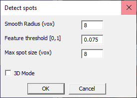
The Detect commands automatically identify all voxels in a 3D image
[satisfying X condition] and return a corresponding ROI layer.
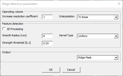
These commands open dialog windows with adjustable parameters.
Operating volume:
Increase resolution coefficient –
Interpolation – Dropdown menu with the choice of Tri-linear,
(default), Nearest neighbor, Wsinc2, Wsinc3, Wsinc4.
Feature detection:
3D Processing – (Checkbox) Toggles on/off 3D mode.
Smooth Radius (vox) – (Default 8) –
Strength threshold [0,1] – (Default 0.05) –
Kernel type – Dropdown menu with the choice of Uniform,
Gaussian, Radial, Raleigh, Median, Minimal SI, Maximal SI.
Output – Dropdown menu with the choice of Ridge Mask (ROI layer),
Elevation Map (real-valued layer), and Ridge Skeletons (ROI layer).
These commands create a new document window with two layers:
1) the original image (labeled [original image]_base), and
2) an ROI layer (labeled Ridges).